
Bus Protection Unit (BPU 1G)
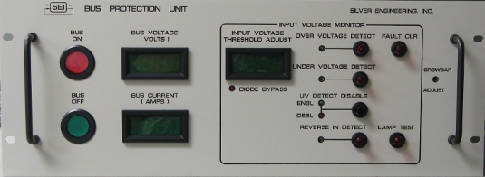 |
| BPU 1G - Front View |
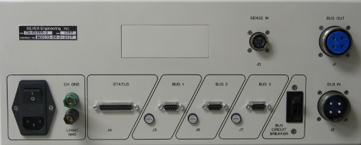 |
| BPU 1G - Rear View |
Any fault condition must be eliminated and the latched fault indication must be cleared before power can be switched on to the unit under test. The BPU 1G intentionally does not have a remote control or external control interface. Not having a remote/external control eliminates the chance that an erroneous or rogue command can inadvertently apply power to the unit under test or change voltage thresholds. The BPU 1G uses comparator circuits to detect fault conditions. The comparator outputs feed a FPGA that implements the logic functions and provides digital filtering. Recessed trim pots set the comparator threshold levels from the front panel. The Over/Under/Reverse thresholds can be displayed while adjustments are made. The BPU 1G also incorporates a separate crowbar circuit for additions over voltage protection. For batter simulator applications, the 150A series diode can be jumpered allowing current to flow either direction. The BPU 1G is available with several options. One option includes a switched AC outlet. The switched outlet can be used to power a large 'Spacecraft is Powered' warning lamp or be used to power an elapsed counter. The elapsed counter can be useful to keep track of burn-in time. Other options include a 120 Volt Version, changing the circuit breaker size, changing the circuit breaker to a fuse, additional auxiliary outputs, etc.
|
| Bus Protection Unit Pricing Information |